Ultra-Simple Theremin Project
Have you always fancied playing the Theremin but don't know where to
get hold of one? Well now you can build a full-featured instrument
for next to nothing! Thanks to the extraordinary powers of the
Raspberry Pi micro-PC, very few external components are required -- the main
job will be building the enclosure and the antennae.
Now even simpler! See last section for how to build it with just one very cheap external IC.
A Theremin produces sound by mixing the signals from two oscillators
running at inaudibly high frequencies. One of these is fixed
(reference oscillator) and the other can be varied by the
capacitance between the player's hand and the pitch antenna. The
mixed signals go through a nonlinear filter (heterodyne detector,
sounds complicated but can be just a diode)
which produces the beat frequency, equal to the difference between
the two oscillators, which you actually hear. The closer the hand to
the antenna, the greater the capacitance between them, the further
the variable oscillator frequency is shifted, and the higher the
beat frequency and hence the pitch of the tone you hear. Volume
adjustment is done by a similar system in which the beat frequency
controls the gain of an amplifier. Full
description here.
So how does the Raspberry Pi help?
The above description sounds simple enough, but in practice it's a
lot more complicated. It is difficult to set up the reference
oscillators to have the exact same frequency as the variable
oscillators, and then get the levels and shapes of the waveforms
right. But all that is easy with computing power! Crucially the
Raspberry Pi has two onboard hardware frequency generators which can
act as reference oscillators, and these are programmable to the
nearest Hz. We just need to build the variable oscillators, which
are simple Colpitts oscillators based on CMOS invertor gates, with
an extra tap in the capacitor chain for the antennae. The outputs go
to extra invertor gates to buffer and square up the signals, still
leaving two free on a CD4069. Instead of an
analogue heterodyne detector, which needs the DC levels set up right
to hit its sweet spot, we use D-type latches (74HC74) that sample the
oscillator outputs at the clock frequencies, producing the beat
frequencies as digital signals which are sent back to the
micro-PC. On the analogue side, that's job done. Even simpler version: Do not even use an external latch to sample the oscillators -- take their outputs straight to the micro-PC and use the onboard SPI controllers to sample them at a programmed frequency.
Circuit diagram here
The software isn't that complicated either. My code is free,
open-source and can be obtained from Github. It
starts by setting the hardware clocks to various frequencies until
it receives a beat frequency signal back from the detector. It then
works out the oscillator frequencies, but sets the hardware clocks
slightly above this so there is always a minimum beat
frequency. This overcomes another problem of analogue Theremins,
that the oscillators can lock together if their frequencies are too
close. So the detected beat is an intermediate frequency (IF) and
the difference is subtracted by the software before generating the
output waveform.
Having worked out the desired pitch and volume, the software
generates the sound. This is done mathematically with the sin() and
exp() functions, generating a series of 16-bit sample values that
are sent to the onboard sound device via the operating system. So
the tone you hear is a pure sine wave.
Putting it all together
Any model of Raspberry Pi will do, so long as it has a 40-pin GPIO
header (smaller ones only have one clock output). The new Pi 4B
has a problem with one of the hardware clocks -- some frequencies
simply do not work. That should be fixed
soon with software updates, but in any case the 4B is far too
powerful for this project!
Your operating system is Raspbian, and you need only the 'lite'
version as no desktop is necessary. This enables an SD card as
small as 4GB to be used, and it does not have to be a fast
one. The software also requires the libasound2-dev and pigpio
packages to be installed from the repository.
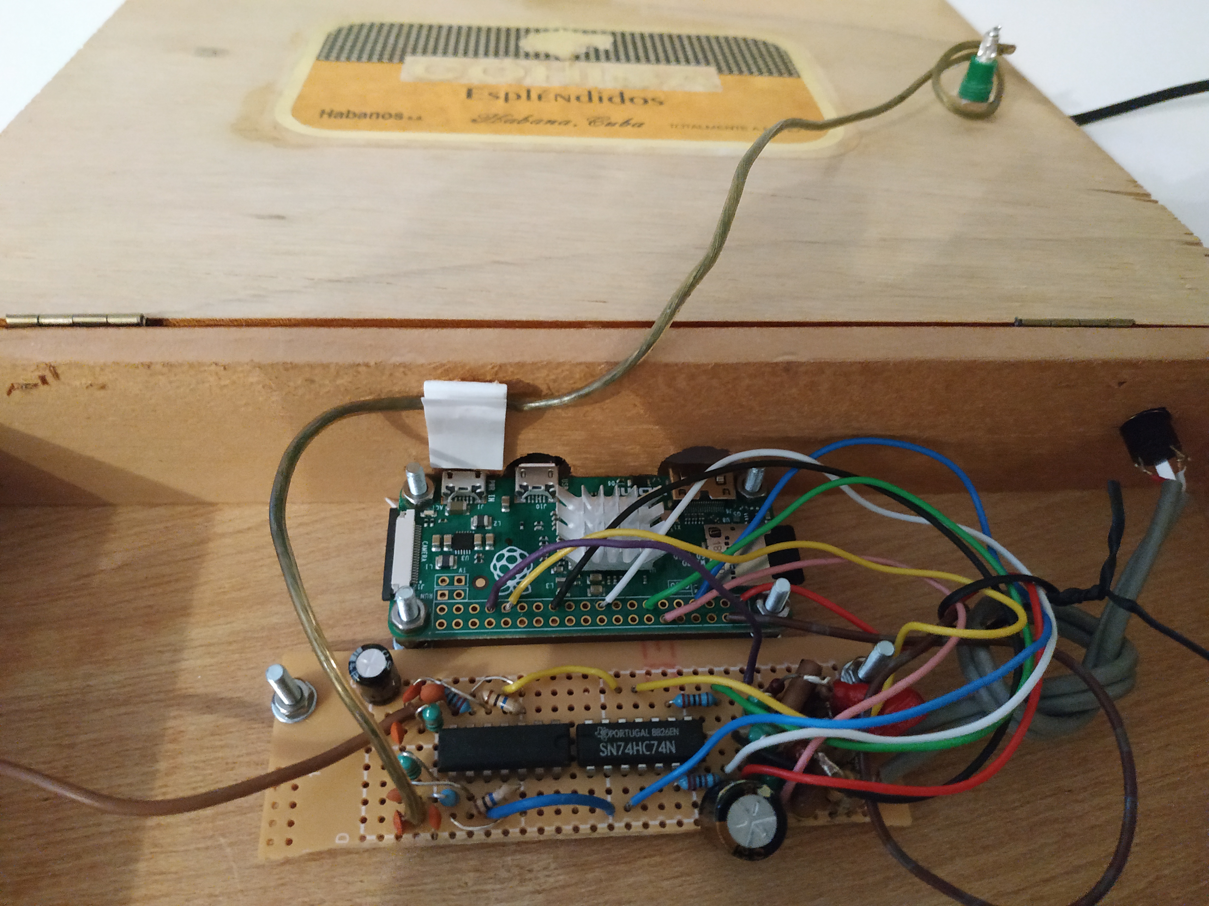
As you see in the above image, my Theremin uses the Pi Zero. This
tiny PC costs next to nothing, but does not have an audio
jack. However the raw PWM signal for the audio can
be sent to GPIO header pins, then put
through a simple filter circuit to get audio output (on the right
on my circuit board in the picture). This circuit allows some
noise from the 3.3v supply rail to get onto the output, which can
be reduced by adding a capacitor between that supply rail and
ground (I used 330uF).
The system needs to be earthed somehow, to complete the circuit
between the player and the antennae. This will be fine if it is
plugged into an external amplifier, but if your theremin is to
include its own speaker it should be earthed via its power
supply. This does not happen if you plug it into a USB charger, so
put the charger inside the box, use a 3-core mains lead and
connect the circuit ground to mains earth.
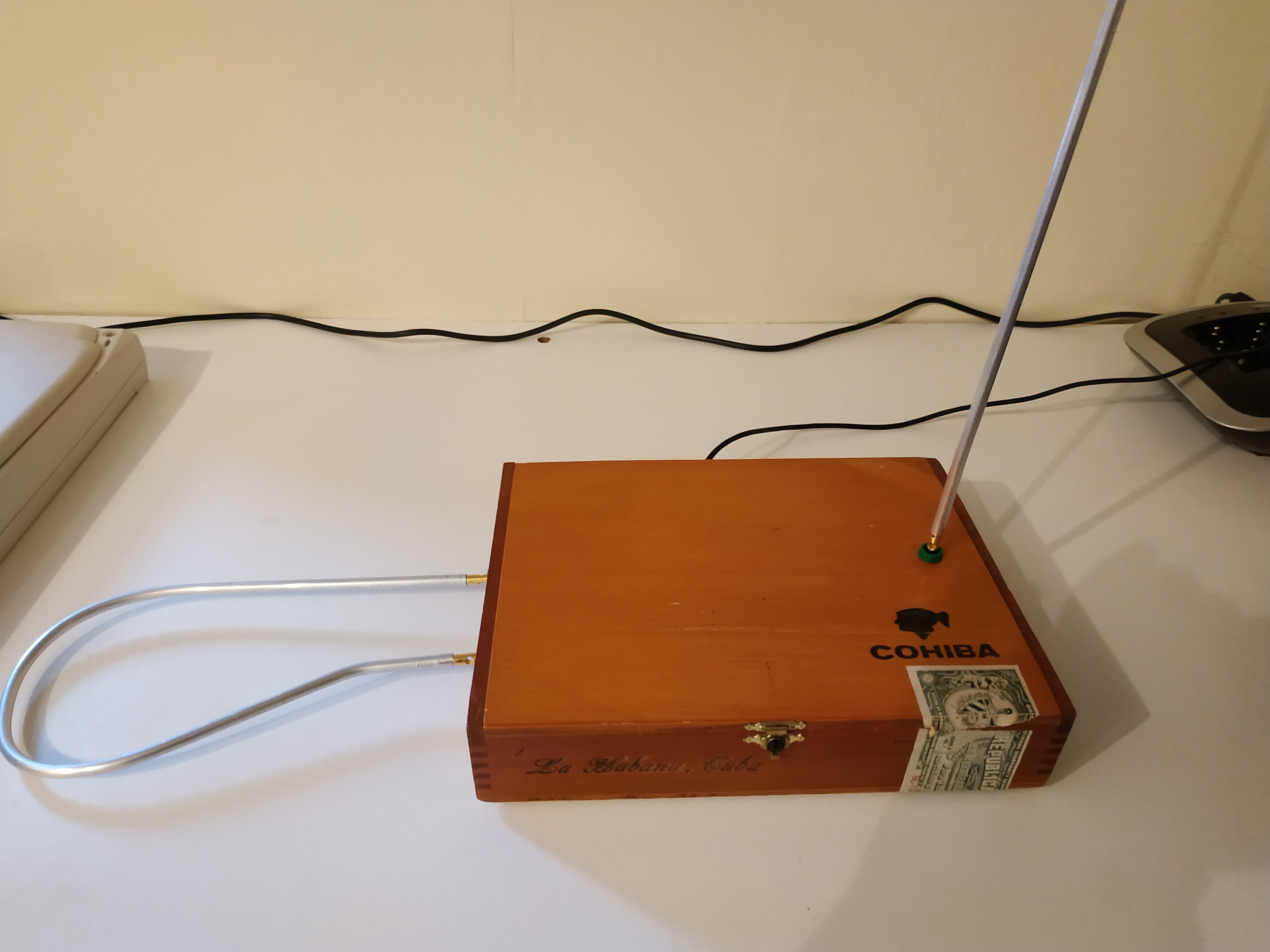
I mounted the whole thing in a Cuban cigar box. My antennae are
made from 6mm diameter aluminium rod (ordered new I'm ashamed to
say, most expensive part of the project) with banana plugs on the
ends connecting to sockets on the case for added portability.
So here's what you've all been waiting for...my rendition
of Star-Spangled Banner on my
home-made Theremin! With massive apologies to everyone,
especially Americans. I just said I designed and built it, never
that I knew how to play it...
Further development
Setup functions
A commercial theremin has a variety of knobs and dials on the
front, by which various operational parameters, such as the
available range of pitch, can be adjusted. Of course, since my
theremin is controlled by software it is easy to alter settings,
but I did not want to clutter the box with controls (and couldn't
be bothered with the wiring). However, since the instrument is
played without touching the antennae, why not touch the antennae
to access the setup functions?
When an antenna is touched, it causes a relatively large change
(about 10kHz) to its associated oscillator frequency. This is
easily distinguished from the changes due to playing the
instrument normally, which are in the order of 2-3kHz. Because a
musician might accidentally touch one antenna while playing, the
only way to stop playing and access the setup system is by
touching both simultaneously. This diagram illustrates the the
state transitions that comprise the setup system -- it's also a
working model of the system in Simile!

OK, so what exactly does this mean? Simple. When you start the
program, you go into the 'Play' state, and can play normally. You
can get out of this only by touching both antennae at once --
"Touch both" on the diagram. This takes you to the "Standby" state
in which no sound is produced. From here you can touch both again
to get back to play, or touch either one to enter one of the setup
sequences.
The setup options are divided into two sequences according to
whether they are to do with pitch or not. Touch the pitch antenna
from standby to go to the pitch settings sequence, starting with
"Pitch range", or touch the volume
antenna to go to the other settings sequence, starting with
"Tone". When in any setting mode, you can play each possible
value for the setting, using the volume antenna to
control the setting itself (the actual volume is fixed), while controlling the pitch in the
normal way with the pitch antenna. To save the setting and move to
the next, touch the pitch antenna while being careful to keep the
volume distance right for the setting you want. Alternatively,
touch the volume antenna to skip to the next setting in the
sequence without changing the current one, or touch both antennae
at once to go
straight back to 'Play'.
So...what are those settings?
Pitch settings
- Pitch range: by default the pitch you play is the actual oscillator frequency, minus the reference frequency. Adjusting this setting allows that frequency to be multiplied or divided by a factor before playing, causing the pitch to go up or down by a fixed musical interval (e.g., an octave) across the playing range.
- Pitch slope: moves the steepest part of pitch adjustment towards or away from the antenna, making it more or less sensitive in the upper range
- Autotune: rounds the pitch to one of a given set of values, stepping between them rather than changing continuously. Comes in six flavours:
- Continuous: no autotune, like trombone
- Chromatic: plays nearest semitone
- Major: plays notes from a major scale, C major by default
- Floydian: plays notes at intervals of a minor 3rd (4 per octave)
- Arpeggio: Plays only Cs, Es or Gs
- Aeolian: Plays harmonics of a low C, i.e., the notes that can be played on an open (valveless) brass instrument
- Tuning: in an autotune mode, sets the baseline for the frequencies that can be played, enabling, for instance, any major scale to be played, or harmonics of any note
Non-pitch settings
- Tone: selects the type of sound produced, from one of the following:
- Sine wave: the default
- Classic: slightly disrorted sine wave, more like an analogue Theremin
- Valve: sound more like a reed instrument
- Triangle: sharper sound
- Sawtooth: creaky sound, good for impersonating a rusty hinge
- Square: very harsh sound, for techno music
- Volume range: Sets the volume of the loudest volume that can be produced when playing
To help you navigate around the settings, I have also included a
generated voice announcement to the audio output naming whichever
state has just been entered. These cam be removed or changed by
removing or changing the .wav files in the installation.
You can use Model A/Model B
These early Raspberry Pis had a smaller GPIO header than the more
recent models, and only one of the hardware clocks was
accessible. However the chips also include two hardware PWM
channels, and one of these is available on GPIO18 of all models
including the A and B. This can be used as one of the reference
oscillators, and I have now fixed the software to allow it to do
so. Just set the REF_P and REF_V constants to 4 and 18 (order
depends on your wiring!) This should also work on the Pi 4B, if you are
desperate to use one of those. However...
- The hardware PWM is used by default to generate the onboard
audio, so this will not work if you are using a PWM as one of
the reference oscillators. However you can still get audio by
plugging in a cheap and cheerful USB sound device, or even on
the HDMI output.
Since there is still one free PWM, it might be possible to
get onboard sound working on one channel only, or even to
add code that sends the audio directly to this PWM and
hence to the left channel of the audio jack without using
the sound API. One channel is all the instrument needs, so
if anyone manages to get this working, let me know!
- The PWM oscillator cannot be set to the nearest Hz, only to
a fraction of the hardware clock frequency of 250MHz (375MHz on
the 4B). However,
since in this system the beat frequency is higher than the audio
output by about 3kHz, we just pick a suitably nearby value for
the reference oscillator and adjust the resulting beat frequency
in software.
If you are using a Model B Rev 0, then you have access to a hardware clock on pin 21. You can use this instead of pin 6, and keep your PWM modules free for generating onboard sound. This clock requires a password to be ORed with the pin number, and the pigpio documentation says using it will probably crash your micro-PC, but I have used it for this project without problems. You do not have pin 27 on this hardware version though, so use pin 23 for the volume beat input instead.
Now even simpler! -- doing without the 74HC74
In this design, the output of each oscillator is sampled at a
frequency generated by the micro-PC to provide a waveform at the
'beat frequency' which controls the generated sound. This sampling
is done by a D-type latch, with a 74HC74 chip conveniently having
one for each oscillator. But the Raspberry Pi also includes a
subsystem that can sample an input signal at a rate set by the
programmer up to 8MHz, with the same flexibility as the PWM
channels described above. It's the SPI (serial peripheral
interface) controller, and except on model A/B there are
two instances of it! So -- can we make the ultra-simple even simpler?
The SPI is designed to exchange data with peripherals in discrete
chunks. The Pi acts as master, sending clock cycles to the slave,
which is supposed to accept and/or generate a single bit of data
at a certain point in each clock cycle. If we are going to use the SPI
to sample our oscillator waveform, the 'peripheral' is completely
ignoring the clock, indeed we don't even connect the clock
pin. All that matters is that the level is sampled at regular
intervals at a frequency we can set up in the code. We know the
clock frequency, having set it, so we can look at bursts of 1s and
0s in the incoming data to find the beat frequency.
The pigpio package we have been using to interface with the header
pins has functions for accessing the SPI modules, but these work
by 'polling' the FIFO registers, i.e., continually checking if a
word can be read or written. This means that if the processor gets
diverted to another task, some samples might be missed, resulting
in the wrong frequency being detected. But there are kernel
drivers available, and these use DMA and/or interrupts to service
the FIFO, making data loss much less
likely. The wiringPi package
uses these drivers -- unfortunately, as published it can only
access the main SPI controller, whereas we want to use the main
and auxiliary controllers to sample the pitch and volume
oscillators respectively. So I have added an edited version to
this project's repository which can do that.
How to use it?
This is only tested with the Raspberry Pi Zero.
- Build the circuit as shown above, but leave out the 74HC74 and connect the oscillator outputs instead to GPIO 9 (pitch) and 19 (volume). Do not connect GPIO 4, 6, 10 and 27.
- Edit the Raspberry's /boot/config.txt file. You may have already tweaked it to get audio from the PWM outputs and to go online via USB, now add:
	  # main SPI controller, can be enabled from raspi-config but may as well do it here
	  dtparam=spi=on
	  # auxiliary SPI controller, cannot be enabled from raspi-config
	  dtparam=spi_aux=on
	  # move cs0 to another pin to avoid clashing with audio (default is 18)
	  dtoverlay=spi1-1cs,cs0_pin=12
	  # make sure peripheral clock always runs at same speed
	  force_turbo = 1
- Now build the SPI-based version of the software:
make ultra
this creates the executable "umts", and you don't even need to be root to run it! (though you must be a member of the spi group)